Flow coefficient
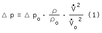
Δ p,  , ρ , ρ | : Pressure loss, Volume flow and Density of component´s point of operation |
| Δ po, o, ρo | : Pressure loss, Volume flow and Density of component´s reference point of operation |
The valve manufacturer Mason-Neilan (MA, USA) introduced in the 1940s
the flow coefficient cv . In the 1950s cv
was introduced as kv
-value (kvs-value for rated travel) in the metric system [Früh 1957].
The flow coefficients cv and kv describe a valve´s reference point of operation
 . The reference fluid
is water (ρo = density of water
at 15,6 ºC) [VDI/VDE 2173-2007 page 8].
. The reference fluid
is water (ρo = density of water
at 15,6 ºC) [VDI/VDE 2173-2007 page 8].
| kv | : o = kv [m³/h] | @ Δpo = 1 [bar] | |||||
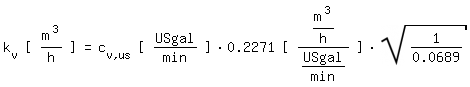
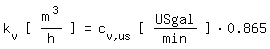
| cv,us | : o = cv,us [USgal/min] | @ Δpo = 1 [psi] | ≡ | o[m³/h] = 0.2271 cv,us [USgal/min] | @ Δpo = 0.0689 [bar] | ||
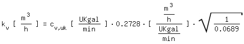
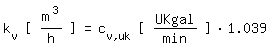
| cv,uk | : o = cv,uk [UKgal/min] | @ Δpo = 1 [psi] | ≡ | o[m³/h] = 0.2728 cv,uk [UKgal/min] | @ Δpo = 0.0689 [bar] | ||
Putting equation (1) to
we obtain the correlation between kv and cv (ρ/ρo=1):
 |  |
 |  |
Equation (1) is derived from equation (2). Equation (2) is derived from the equation of Darcy-Weisbach
:
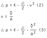
| K | : Dimensionless resistance coefficient (friction factor) of the component. K is assumed to be constant. |
| v | : Average speed in the characteristic cross section |
| A | : Characteristic cross section |
| d | : Inner diameter of the characteristic cross section. For valves as a general rule the characteristic diameter equals the nominal diameter DN. |
The resistance coefficient K is assumed to be constant. This assumption
is correct for completely turbulent flow. In many other cases the inaccuracy is acceptable.
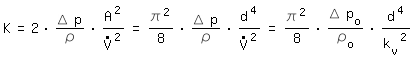
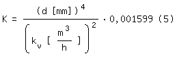
Putting equation (3) to K and with A = π/4 d2 the correlation between
resistance coefficient K and flow coefficient kv becomes equation (5):
 |  |
By lowering the pressure behind a valve the volume flow can´t rise without limits. Pressures below the vapour pressure lead to cavitation. The noise level rises and at maximum cavitation we face choked flow. According to [VDI/VDE 2173-2007 page 10] we can note for control valves:
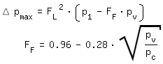 |
p1: Absolute pressure at the inlet pv: Vapour pressure pc: Critical pressure (Water: pc=221,2 bar) |
|
More detailed information (including not turbulent flow) can be found in [DIN EN 60534 2012].
| Literature |
| [DIN EN 60534 2012] DIN EN 60534-2-1: Stellventile für die Prozessregelung, Beuth-Verlag Berlin, Januar 2012 |
| [Früh 1957] K.F.Früh: Berechnung des Durchflusses in Regelventilen mit Hilfe des kv-Koeffizienten, Regelungstechnik Heft 9; 5. Jahrgang 1957 |
| [VDI/VDE 2173-2007] VDI/VDE 2173: Stömungstechnische Kenngrössen von Stellventilen und deren Bestimmung, Beuth-Verlag Berlin, September 2007 |