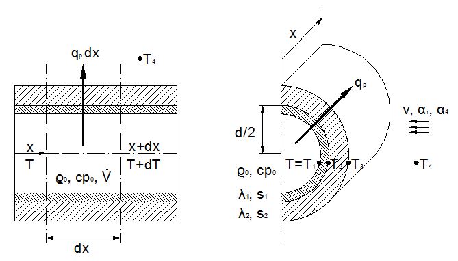
Turbulent flow in the pipe. Medium temperature changes only with coordinate x. Pipe
wall and insulation temperature change with x and r. Heat transfer between medium and pipe wall
is so strong, that the inner pipe wall temperature equals medium temperature
(α 1 => ∞,
T=T1).
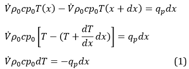
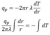
Medium´s change of enthalpie from x to (x+dx) equals the radial heat transfer
(qp·dx) in tube section dx:
qp > 0: cooling downqp < 0: heating
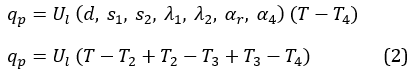
The heat flow per unit length qp at x depends on the geometry
(d, s1, s2),
the operational thermal conductivities of pipe wall and insulation
(λ1, λ2),
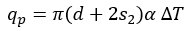
the heat transfer between insulation and environment by radiation and convection
(αr, α4) and
the temperature difference between medium and environment (T-T4):
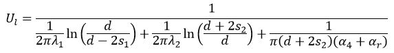
Ul :
thermal transmittance per unit length
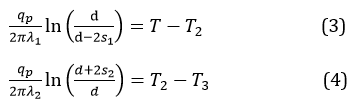
Temperature differences (T-T2), (T2-T3) and
(T3-T4) can be derived from the laws for thermal conduction and
convection. The heat flow per unit length qp stays constant in all 3
sections (pipe wall, insulation, environment), since neither pipe wall nor insulation pick up
or release heat (temperature profile doesn´t change with time).
Thermal conduction
External heat transfer(convection and radiation)
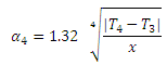
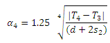
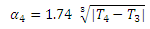
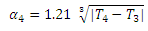
According to [DIN EN ISO 12241, pages 17-19] the following set of formulas
describes free convection with x, d, s [m], α4 [W/(m² K)]. Laminar flow prevails for
horizontal piping, turbulent flow for vertical piping.
vertical pipe
horizontal pipe
laminar
x³ |T4-T3| <=10 [m³ K]
(d+2s2)³ |T4-T3| <=10 [m³ K]
turbulent
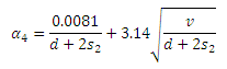
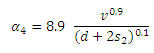
According to [DIN EN ISO 12241, pages 17-19] the following set of
formulas describes forced convection with v [m/s], d,s [m],
α4 [W/(m² K)] :
vertical pipe and horizontal pipe
laminar
v (d+2s2) <= 0.00855 [m/s²]
turbulent
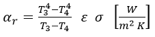
According to [DIN EN ISO 12241, pages 17-20]radation can be calculated as follows:
ε: Emissivity [-]
σ: Stefan-Boltzmann-Constant
(radiation constant of the black body)
5.67 x 10⁻⁸ [W/(m² K4)]
T3, T4 [K]
Surface
ε [-]
Aluminium blank
0.05
Aluminium oxidized
0.13
Zink coated steel blank
0.26
Zink coated steel dusty
0.44
not metallic
0.94
Substituting equations (3), (4) and (5) into (2) results in a formula for the thermal
transmittance per unit length:
Pipe suspensions, valves and flanges enlarge the thermal transmittance per unit lenght.
[DIN EN ISO 12241, pages 35-37, 40-41] and
[VDI 2055, pages 35-37, 150-153] indicate the amount by which
Ul has to be raised. If the first suspension is of no importance, heat loss
of the suspensions for pipe systems with a span of 1 meter can be approximated by a surcharge
of 15% (indoor installation) and 25% (outdoor installation). How those surcharges develop with
increasing span shows the following table:
Span [m]
1
1.5
2
2.5
3
3.5
4
4.5
5
Indoor installation
15
10
7.5
6
5
4.3
3.8
3.3
3
Outdoor installation
25
16.7
12.5
10
8.3
7.1
6.3
5.6
5
Surcharge [%] for Ul for pipe suspensions neglecting
the first suspension
If you want to calculate the losses of all suspensions, you have to multiply
the table values by 2/1=2 when calculating 2 suspensions, by 3/2=1.5 with 3 suspensions,
by 4/3=1.333 with 4 suspensions, by 5/4=1.2 with 5 suspensionsand so on.
Example: span 2[m], 10 suspensions,
Outdoor installation: Supplementary value for plant related thermal bridges = 10/9 x 12.5 = 13,9%
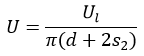
Thermal transmittance of a cylinder can be calculated as follows
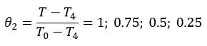
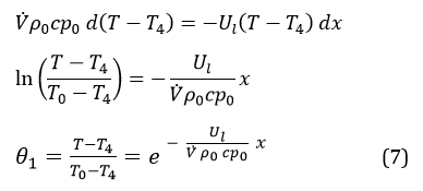
Substituting equation (2) into equation (1) leads to equation (7). Equation (7) describes
the temperature profile of the medium along the pipe axis:
Thermal transmittance Ul and surface temperature T3
are calculated at every node (x = 0, x = x1, x = x2).
Dew formation on the pipe surface occurs if medium temperature is below ambient temperature and partial
water vapor pressure equals saturation pressure at surface temperature. Vapour barrier layers
(aluminum foil) minimize dew formation.
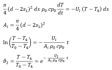
Instationary State
When the flow stops the temperature profile in every tube section dx changes with time. Neglecting axial heat transfer
and the heat capacity of pipe wall and insulation we can write:
It is assumed that no phase change occurs in the medium. Thermal transmittance Ul
and surface temperature T3 are calculated for the following nodes
Literature
[DIN EN ISO 12241] DIN EN ISO 12241:2008-11 Thermal insulation for
building equipment and industrial installations - Calculation rules (ISO 12241:2008);
German version EN ISO 12241:2008
[VDI 2055] VDI 2055 July 1994 Thermal Insulation for Heated
and Refrigerated Industrial and Domestic Installations, Verein Deutscher Ingenieure -
Calculations, Guarantees, Measuring and Testing Methods, Quality Assurance,
Supply Conditions

 Ul :
thermal transmittance per unit length
Temperature differences (T-T2), (T2-T3) and
(T3-T4) can be derived from the laws for thermal conduction and
convection. The heat flow per unit length qp stays constant in all 3
sections (pipe wall, insulation, environment), since neither pipe wall nor insulation pick up
or release heat (temperature profile doesn´t change with time).
Ul :
thermal transmittance per unit length
Temperature differences (T-T2), (T2-T3) and
(T3-T4) can be derived from the laws for thermal conduction and
convection. The heat flow per unit length qp stays constant in all 3
sections (pipe wall, insulation, environment), since neither pipe wall nor insulation pick up
or release heat (temperature profile doesn´t change with time).

 ε: Emissivity [-]
σ: Stefan-Boltzmann-Constant
(radiation constant of the black body)
5.67 x 10⁻⁸ [W/(m² K4)]
T3, T4 [K]
ε: Emissivity [-]
σ: Stefan-Boltzmann-Constant
(radiation constant of the black body)
5.67 x 10⁻⁸ [W/(m² K4)]
T3, T4 [K]
 Pipe suspensions, valves and flanges enlarge the thermal transmittance per unit lenght.
[DIN EN ISO 12241, pages 35-37, 40-41] and
[VDI 2055, pages 35-37, 150-153] indicate the amount by which
Ul has to be raised. If the first suspension is of no importance, heat loss
of the suspensions for pipe systems with a span of 1 meter can be approximated by a surcharge
of 15% (indoor installation) and 25% (outdoor installation). How those surcharges develop with
increasing span shows the following table:
Pipe suspensions, valves and flanges enlarge the thermal transmittance per unit lenght.
[DIN EN ISO 12241, pages 35-37, 40-41] and
[VDI 2055, pages 35-37, 150-153] indicate the amount by which
Ul has to be raised. If the first suspension is of no importance, heat loss
of the suspensions for pipe systems with a span of 1 meter can be approximated by a surcharge
of 15% (indoor installation) and 25% (outdoor installation). How those surcharges develop with
increasing span shows the following table:
 Substituting equation (2) into equation (1) leads to equation (7). Equation (7) describes
the temperature profile of the medium along the pipe axis:
Substituting equation (2) into equation (1) leads to equation (7). Equation (7) describes
the temperature profile of the medium along the pipe axis:
 Thermal transmittance Ul and surface temperature T3
are calculated at every node (x = 0, x = x1, x = x2).
Dew formation on the pipe surface occurs if medium temperature is below ambient temperature and partial
water vapor pressure equals saturation pressure at surface temperature. Vapour barrier layers
(aluminum foil) minimize dew formation.
Thermal transmittance Ul and surface temperature T3
are calculated at every node (x = 0, x = x1, x = x2).
Dew formation on the pipe surface occurs if medium temperature is below ambient temperature and partial
water vapor pressure equals saturation pressure at surface temperature. Vapour barrier layers
(aluminum foil) minimize dew formation.
 It is assumed that no phase change occurs in the medium. Thermal transmittance Ul
and surface temperature T3 are calculated for the following nodes
It is assumed that no phase change occurs in the medium. Thermal transmittance Ul
and surface temperature T3 are calculated for the following nodes